
A stress model and a piping model start as the same pipe. By the end of a project they are two files, and somebody has redrawn one of them to match the other.
CPD, the cloud Piping Designer in EngCoSuite, could already export a CAESAR II neutral file. It can now read one too. That gives you a round trip: import a .cii, edit the line in 3D, export it back.
What comes in
Upload a .cii file (version 10.x or 13.0, up to 8 MB) and CPD rebuilds the line from the neutral file's node coordinates.
- Bends become elbows. CPD works out the tangent length from the bend radius and the angle, and cuts it back from both adjoining legs. If the legs are too short for the radius, it reduces the radius and tells you.
- Rigids become valves and flanges (in 13.0 files, which carry the type).
- Restraints become the supports piping designers actually use. An anchor stays an anchor. A restraint in the vertical direction becomes a rest, and if it also acts along the other axes it becomes a rest with a hold down. Across the pipe it becomes a guide, along the pipe a line stop. The gap on a guide or line stop is kept.
- Files saved with the Y axis vertical are rotated into CPD's Z-up convention.
Anything CPD can't map is skipped with a warning, and the data is still stored in the file rather than thrown away. Reducers and tees aren't inferred from the neutral file, so a change of diameter comes in as a plain junction and CPD tells you.
What goes out
The export writes a CAESAR II 13.0 neutral file. An elbow becomes a bend, valves and flanges become rigids, and each supported node gets its restraint record: anchor, rest (with a friction value of 0.3), guide and line stop (both with the gap in mm). Wall thickness for each element comes from its pipe schedule, using the same size and wall tables the rest of CPD uses.
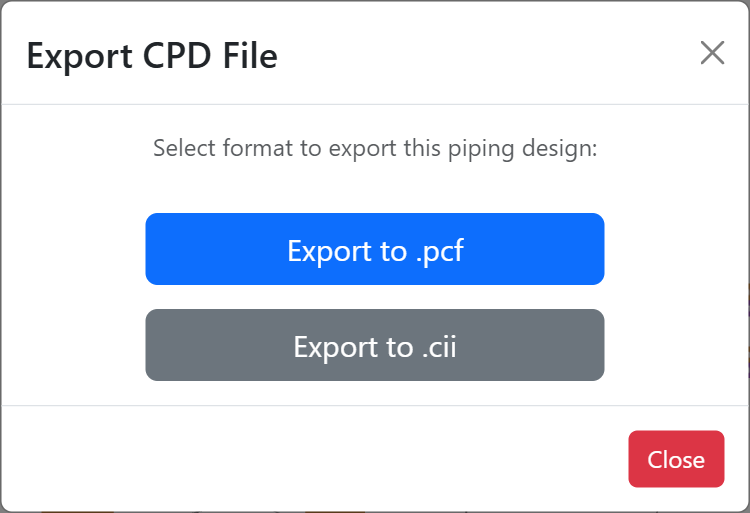
The same model exports to PCF as well, so one 3D line can feed both the stress analysis and an IsoMet isometric.
Review it with the stress engineer
Once the line is in a review workflow, CPD opens view-only for the reviewer. They click an element, a node or any point on the model to leave a comment, and the comment remembers the camera view they were using, so the stress engineer can see what the designer saw.
Two limits you should know
I'd rather say these here than have you find them on a Friday afternoon.
- Process data in the exported file is a placeholder. Temperature, pressure, material, insulation and corrosion allowance are not yet carried by CPD, so the exported file uses default values. Set them in CAESAR II before you run anything. The file's notes list every placeholder.
- Only the first piping system is exported. A CPD file can hold several separate runs. If it does, EngCoSuite warns you and exports the first one.
Spring cans and hangers are written as rigid supports, and a hold down is written as a two-way Z restraint, because I don't yet have a CAESAR II sample with those records to copy from. If you have one saved from CAESAR II 15.1 containing a hold down, a spring hanger, a one-sided guide and a tee with SIFs, send it over and I can make the export match.
Over to you
If you move between piping and stress models, which direction costs you more time: designer to stress, or stress back to designer?