
Piping Systems
Design pipe networks visually, solve flow distribution and pressure losses, and generate detailed engineering reports — all in your browser.
Overview
Piping Systems is a browser-based tool for designing and analysing pipe networks. Draw your system visually — connect nodes, add pipes and fittings, define pumps and tanks — then solve for flow distribution, pressure losses, and velocities using industry-standard Darcy-Weisbach calculations.
Compare scenarios side by side (e.g. normal vs. fire case), generate professional reports with embedded system diagrams, and share results via secure viewer links.
Key Features
Visual System Designer
Drag-and-drop canvas with a library of node types (tanks, pumps, tees, vessels) and pipe edges. Connect components, add fittings from a built-in catalogue, and configure control valves and restriction orifices.
Flow Distribution Solver
Iterative solver using Darcy-Weisbach friction and K-factor minor losses. Handles parallel paths, branch points, and closed recirculation loops with automatic convergence balancing.
Pump Curve Analysis
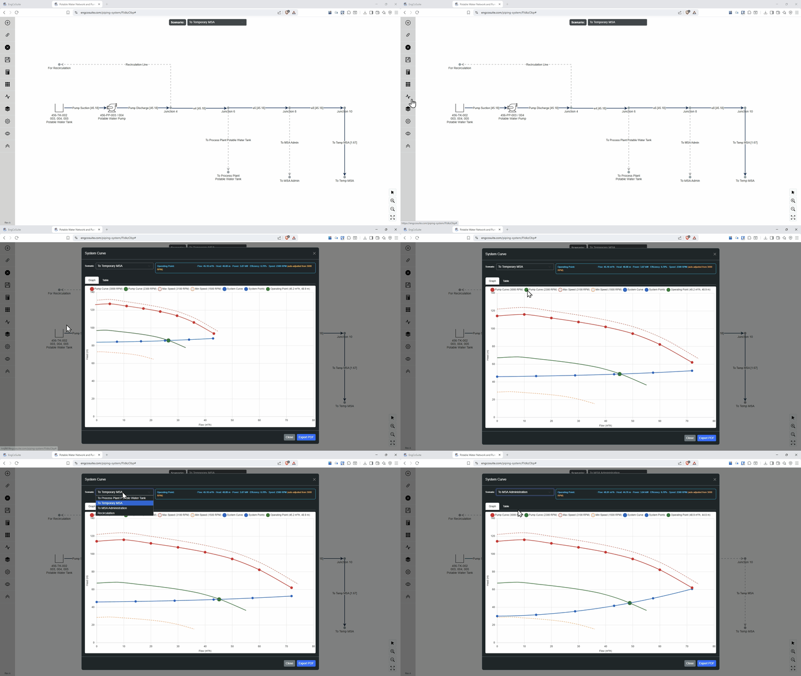
Enter pump head-flow curves and let the engine find the operating point by intersecting the pump curve with the computed system resistance curve. Supports variable speed via affinity laws.
Restriction Orifice Design
Design orifices by specifying a target flow — the engine solves for the required diameter. Or enter a known diameter for analysis. Multiple orifices per system, editable Cd coefficient.
Multi-Scenario Comparison
Run multiple scenarios per system (e.g. normal, fire, maintenance). Compare flows, pressures, and velocities side by side in the cross-scenario summary table.
Reports & Sharing
Generate detailed reports with system diagrams, per-scenario pipe tables, and pump operating data. Export to PDF or share a secure viewer link with your team and clients.
How It Works
Draw Your System
Place nodes on the canvas and connect them with pipe edges. Add fittings, valves, and orifices to each pipe. Define tank levels, pump curves, and scenario-specific settings.
Solve
Click Calculate. The engine solves flow distribution, friction losses, fitting losses, orifice pressure drops, and pump operating points. Results appear instantly in the results table.
Report & Share
View detailed results in the browser, generate a PDF report, or share a read-only viewer link. All work is revision-controlled and saved automatically.
Calculation Engine
The engine uses industry-standard methods for accurate hydraulic analysis:
- Friction: Darcy-Weisbach with Colebrook-White (Swamee-Jain approximation)
- Minor losses: K-factor method for fittings, valves, elbows, and orifices
- Flow solver: Iterative path propagation with branch-point pressure balance
- Pump curves: Polynomial fitting with bisection operating point search
- Variable speed: Affinity law scaling (Q ∝ r, H ∝ r², P ∝ r³)
- Orifice sizing: Binary search on β ratio to match target flow to available ΔP
Full calculation documentation is available in the technical reference.
Ready to Get Started?
Design your first piping system in minutes — no software to install.
Sign Up Free